Ni-CDS
Non-intrusive Cavitation Detection System
A new tool to help achieve Quiet Oceans and protect Marine Fauna
What is Ni-CDS?
The Non-intrusive Cavitation Detection System is a monitoring system which automatically detects the existence of undesirable cavitation by monitoring the vibration transmitted by the propeller/s to the hull. Using TSI’s patented algorithm, cavitation is detected in terms of both occurrence and intensity. SOFTWARE + HARDWARE
Main Benefits
For the vessel and the environment.
In addition to its main functionalities, Ni-CDS is a tool to mitigate ocean noise and protect marine wildlife.
Accurate control of cavitation intensity
allowing navigation in noise restricted areas.
Enhanced lifetime of cavitation-affected element:
rudder, propeller, etc.
On board vibration level reduction.
Improved propulsive performance of the vessel.
Improving the vessel performance in terms of emission and fuel consumption optimization.
Improvement of the underwater radiated noise signature.
Cost-effective
and non-intrusive installation.
Adapted to your needs
Flexible and adaptable to customer’s needs.
Optimization of the use of the propeller.
This system ensures optimum propeller operation.
Control of “silent modes”
for Navy Ships and submarines
Detection of undesirable operating conditions.
Main features
- Non-intrusive and easy to install system.
- Stand-alone configuration and/or integrated in the vessel’s systems.
- Visual and acoustic alarms.
- Display screen in the bridge navigation systems and in the engine control room.
- Identification and continuous monitoring of propeller cavitation status.
- Easy and fast integration of processing hardware and display screens.
- Data logging and exporting for statistical purposes. Generation of a database on propeller behavior.

Instalaltion
- Ni-CDS installation is non-intrusive: no hull penetrations, holes, or any other severe interventions are required.
- No need for dry dock services, leading to time and economic savings.
- On board installation of sensors for accurate detection of the propeller cavitation existence and level of intensity.



Commissioning & Calibration
- Ni-CDS’s components can be provided with a calibration certificate.
- During the commissioning of the Ni-CDS, TSI includes an onboard initial verification test in the installation stage and subsequent verification assessments for ensuring the proper performance of the system throughout its lifetime.
- Calibration associated with draft. Can be performed by non-experts.

Signal Processing
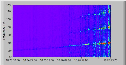
- Accelerometer signals are registered and processed by a patented algorithm (PCT/ES2017/070580), which automatically establishes a vibration threshold that defines the inception of cavitation.
- The system enables analysis of the operating conditions in which cavitation occurs by analysing the accelerometer signals and other quasi-static parameters.

User Interface
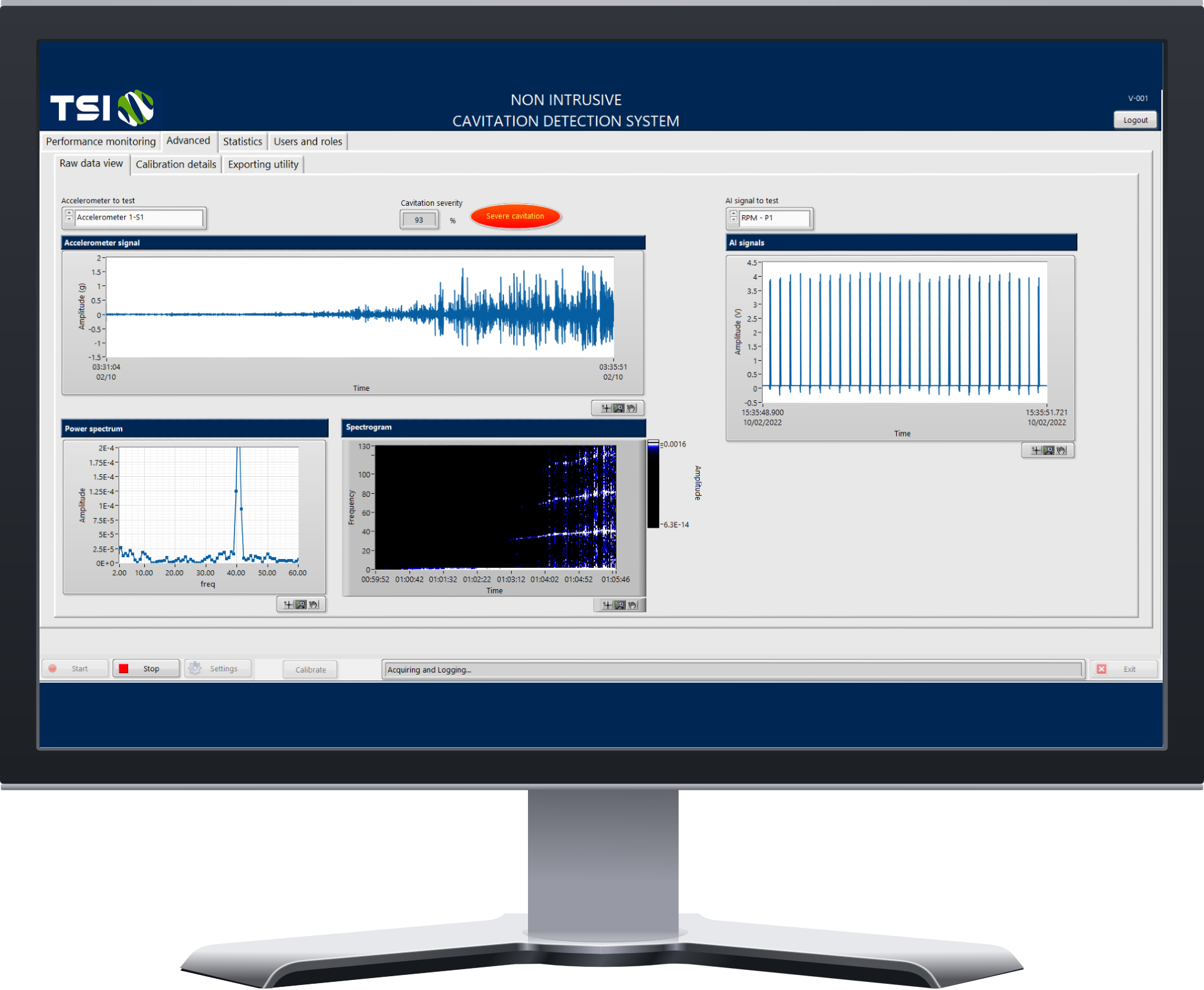
Ni-CDS’s user interface is intuitive and user-friendly. It offers quick access to data/information to operate the ship efficiently and safely. The main tabs for the control and use of Ni-CDS are:
The performance Monitoring tab
The performance Monitoring tab displays indicators of the propeller condition with a visual alarm, a map of the cavitation, and recent time evolution of cavitation.
The statistics tab
The statistics tab shows the cavitation historic data, the evolution of cavitation in a specific operating condition, and the cavitation path, which plots the cavitation spatially with the GPS signal.
The advanced tab
The advanced tab plots the historic data registered by the system and useful graphs related to the algorithm. It also has calibration, test, and data download tools.
The settings window
The settings window allows configuration of sensor settings, vessel features, and acquisition/storage logic by user-friendly panel.
System specifications
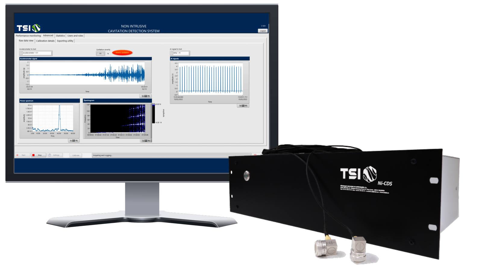
Hardware + Software
- Permanent monitoring by means of accelerometers.
- Acquisition Card: +/- 30 V 24-bit resolution.
- Sample Rate: 102.4 kHz per channel.
- Remote access via Ethernet/WAN/LAN
- Monitoring rate: Every second.
- Power consumption:<40W.
- Electronic unit dimensions: 482.2 x 263.0 x 132.5 mm.
- Two screens: control room and bridge.
DESCRIPTION OF SINGLE-AXIS SYSTEM COMPONENTS
Data acquisition system (SW and HW) in 3U 19″ rack mount housing, including:
- 3 dynamic channels (accelerometers)
- 4 static channels (tachometer + configurable optionals: blade pitch, rudder angle, etc.)
3 Accelerometers + cable to data acquisition system.
Tachometer + cable to data acquisition system.
Interface consisting of a 12″ touch-screen display + cable to data acquisition system.
Optional: Cat7 Ethernet cable for MODBUS connection to DCS/SCADA.
COMPONENT DESCRIPTION OF THE SYSTEM WITH TWO AXES
Data acquisition system (SW and HW) in 3U 19″ rack mount housing, including:
- 6 dynamic channels (accelerometers)
- 8 static channels (4/axis: tachometer + optional configurable: blade pitch, rudder angle, etc.)
6 Accelerometers + cable to data acquisition system.
2 Tachometers + cable to data acquisition system.
Interface consisting of a 12″ touch-screen display + cable to data acquisition system.
Optional: Cat7 Ethernet cable for MODBUS connection to DCS/SCADA.
Validated in real-scale tests during vessel navigation:
Experimentally validated by means of full-scale tests during the navigation of different types of ships, as well as in Cavitation Tunnel.
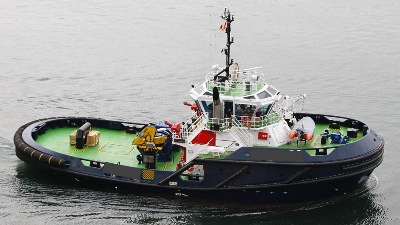
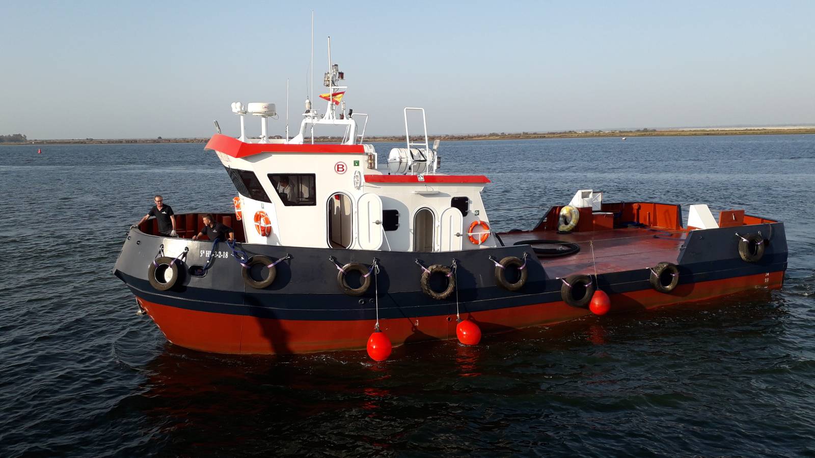
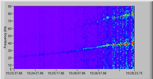
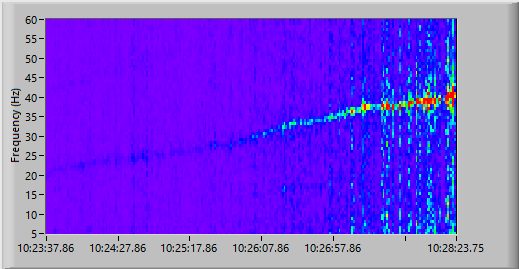
Note: The cavitation indicators of each vessel do not correspond to their images.
FAQ
Frequently Asked Questions If you have any additional questions you can contact us:
Should holes be drilled in the hull for installation?
Ni-CDS is a NON-intrusive, easy to install system. No drilling is required for installation.
How can I integrate the system into my ship command platform?
The Ni-CDS system has optional analog and digital outputs that allow it to be connected to any control platform: – MODBUS TCP: publication of all variables of interest on a MODBUS map that can be accessed from the command platform via Ethernet connection. – Analog outputs: current/voltage outputs equivalent to variables of interest. Display of cavitation indicators and other variables on analog clocks or by means of light signals.
Is technical support required for installation and calibration?
Technical support is required to install the device. Subsequent calibrations can be done by the ship’s operators without any problem.
If I am not an expert, can I use it?
The Ni-CDS design is intuitive and easy to use. No prior knowledge is required. Our technicians will give you a brief tour of the system once you are up and running.
How many sensors are needed?
Depending on whether the system consists of one or two propellers, between 7 and 14 sensors are required.
What is the delivery time once the order is placed?
See the different options we have available.
Download the PDF brochure
Get the document in full resolution PDF.
Datasheet
See Ni-CDS technical specifications.
Learn more about Ni-CDS
If you would like more information, you can request a no-obligation meeting. Click on the “I WANT TO KNOW MORE ABOUT NI-CDS” button to be contacted by our sales department, or call our offices.
